Electrical
Electrical design
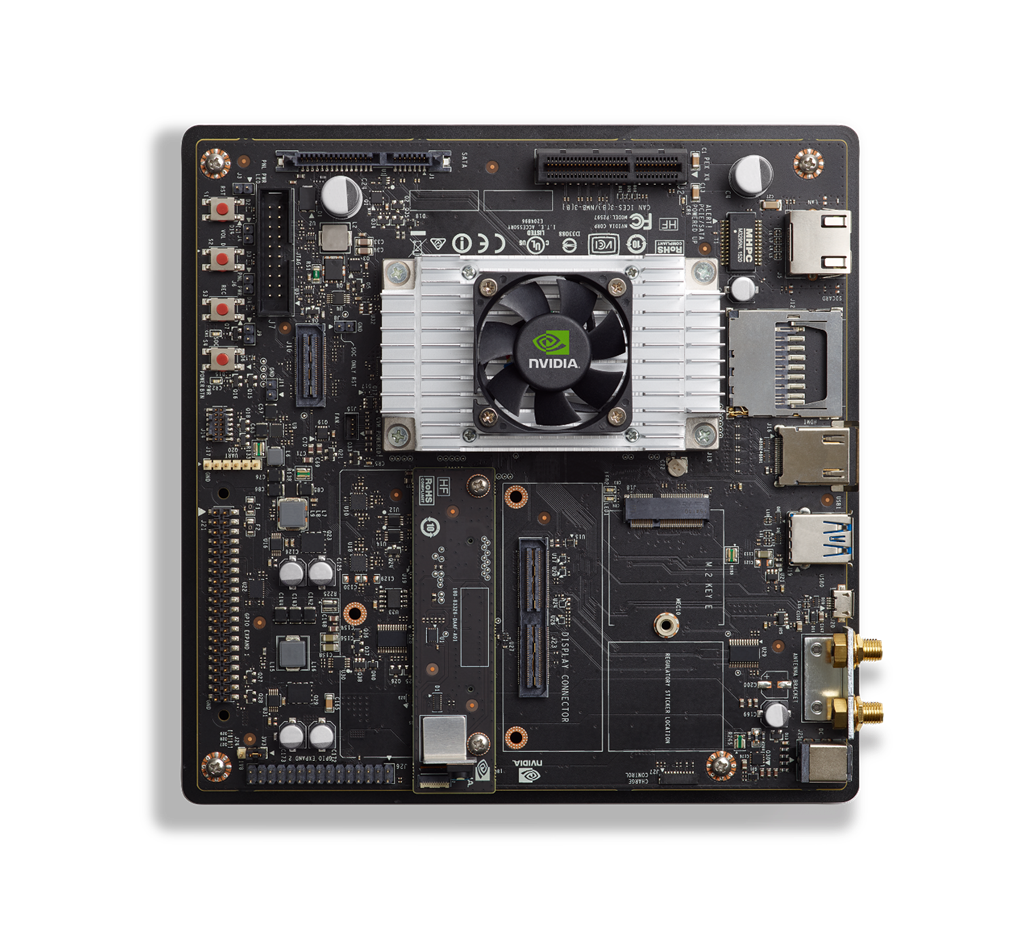
Main Computer
Jetson TX2
Basic Specs (Advanced)
- CPU
- ARM® Cortex® A57 MPCore (Quad-Core) Processor
- NVIDIA Denver 2 (Dual-Core) Processor - Pascal GPU
- 256 NVIDIA® CUDA® cores - Memory
- 4GB | 128-bit LPDDR4 DRAM - Storage
- 16GB eMMC 5.1 Flash Storage - Networking
- 10/100/1000 BASE-T - CSI Camera
- 12 lanes (3x4 or 5x2)
- MIPI CSI-2 D-PHY 1.2 (2.5Gb/s per lane, total up to 30Gbps) - Display Controller
- Two multi-mode eDP 1.4 | DP 1.2a | HDMI 2.0a/b | 1 x2 DSI (1.5Gbps/lane)
- Maximum Resolution (eDP/DP/HDMI): (up to) 3840x2160 at 60Hz (up to 36 bpp) - Multi-Stream HD Video and JPEG
- Video Decode 2x 4K60 | Video Encode 1x 4K60 - Peripheral Interfaces
- xHCI host controller with integrated PHY (up to) 1x USB 3.0(Gen1), 3x USB 2.0
- PCIe 1 x2 + 1 x1 (Gen2), Root Port Only
- SD/MMC controller (supporting eMMC 5.1, SD 4.0, SDHOST 4.0 and SDIO 3.0)
- 3x UART
- 2x SPI
- 4x I2C
- 1x CAN
- 4x I2S
- GPIOs
- 1x SD Card/SDIO - Mechanical
- Module Size: 69.6 mm x 45 mm | 260 pin edge Connector - Operating Requirements
- Temperature (TJ)*: -25°C ~90°C (typical)
- Supported Power 15W
- Power Input: 5V
Developer Kit
Revision: B02 / B04
Basic Specs (Advanced)
Jetson HAT Design V1.0
Writing In Progress
Idea
The idea of a Jetson HAT comes from the common name of Raspberry Pi HATs (Hardware Attached on Top).
Goals
- Create a PCB HAT for the Jetson carrier.
- Create a compact and versatile board to interface sensors with.
- Create a simple power distribution system for sensors and for the Jetson carrier board.
Design
Physical
Jetson TX2 Carrier
Overall size
The Jetson TX2 carrier board has overall dimensions of 170 mm x 170 mm (6.7 in x 6.7 in). The mounting screws for the carrier board are also located at three of the four corners, forcing the use of a very large PCB for the HAT. We felt that matching the size of the carrier board would also help us with laying out all the components we want to include on the PCB.
Interferences
The Jetson TX2 carrier board has a few ports that cannot be blocked by the HAT design. These include:
- SATA interface
- PCIE interface
- Power and reset buttons
The carrier board also has a large heatsink that protrudes from the middle of the board to cool the TX2 module. This required us to make a large cutout in the center of the PCB.
Electrical
Power
One of the goals of the board was to clean some of the power distribution of smaller components on the robot. This includes the power supply of the Carrier board that the HAT is attached to. The carrier board comes with a power supply rated for 19v 4A, this definitely includes a large overhead as the board normally only draws about 7.5 watts. However, as more peripherals are attached to the carrier it can draw more power.
Going off the idea that the carrier board is provided with a 76-watt power supply we want to be able to provide at least that much power to the carrier from our HAT design if possible.
USB-C PD 3.0
One idea is to utilize the growing USB-C PD 3.0 standard to allow for 100 watts of power delivery by battery packs and basic wall chargers.
If the board is to be powered using the 3.0 standard then it cannot exceed 100w of power draw.
Communication
Thermal
Cooling
Electrical 2024 Meeting notes
11/15/23
Meeting goals
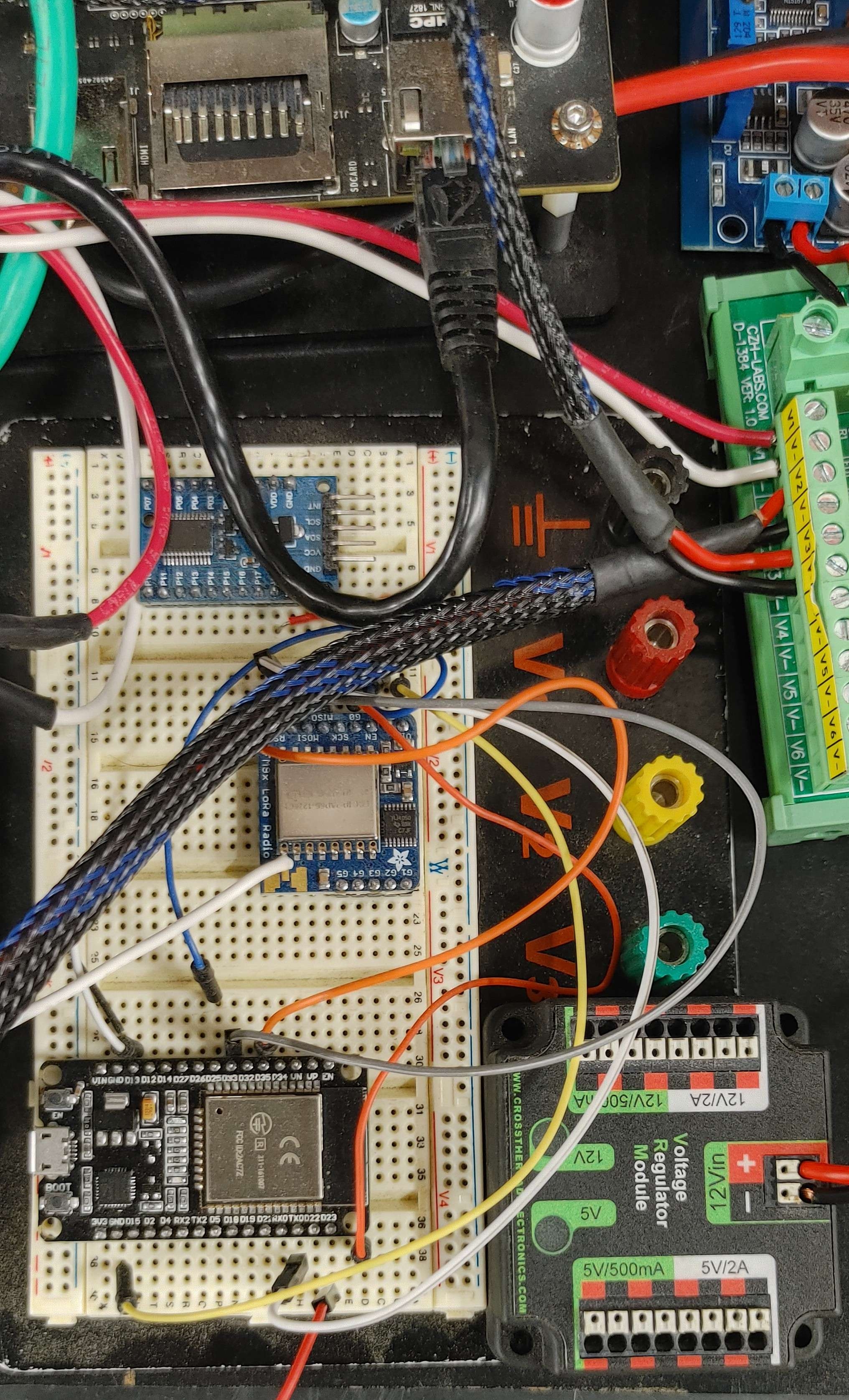
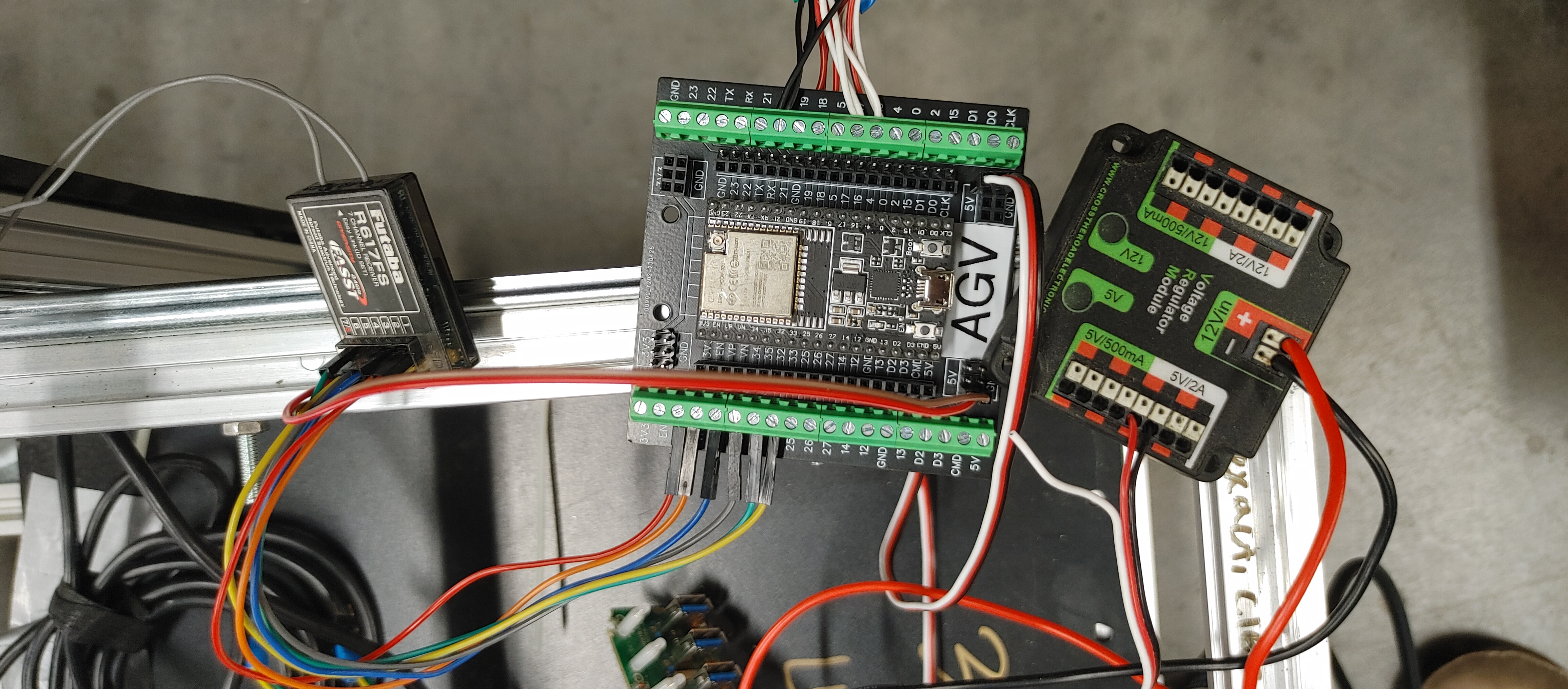
- Cleanup wiring on the robot
- Add Logic Level Shifter Schematic to the main schematic
Meeting Notes
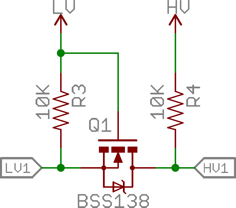
We added the logic level shifter high voltage selector circuit. This circuit consists of 4 pin headers with 3 of the pins in line and a fourth pin in parallel with pin 2. This will allow us to select the output voltage of the circuits using a jumper between pin two and any of the other 3 pins.
What was completed?
- Made logic level shifter High Voltage selector circuit
What is in progress?
What is the goal for the next meeting?
Pictures
11/8/23
Meeting goals
- Cleanup wiring on the robot
- Add Logic Level Shifter Schematic to the main schematic
Meeting Notes
What was completed?
- Add Logic Level Shifter Schematic to the main schematic
What is in progress?
- Cleanup wiring on the robot
- Add Logic Level Shifter Schematic to the main schematic
What is the goal for the next meeting?
- Cleanup wiring on the robot
- Add Logic Level Shifter Schematic to the main schematic
Pictures
11/1/23
Meeting goals
- Cleanup wiring on the robot
- Work to switch breadboard for breakout board
- Logic Level Shifter Schematic
Meeting Notes
What was completed?
- USB hub power
- Decision-making for relays to cut PWM signal
- Updated PCB design to use 9-pin data connections
What is in progress?
- Cleanup wiring on the robot
What is the goal for the next meeting?
- Cleanup wiring on the robot
- add Logic Level Shifter Schematic to the main schematic
Images

1/22/24
Meeting goals
- Determine and delegate tasks for the semester
- Introduce all new members to Fusion360 and planka.
Meeting Notes
What was completed?
- Introducing everyone to software
What is in progress?
- Dividing of components into new pages on Fusion360
What is the goal for the next meeting?
- Delegate tasks out to everyone so we can begin work.
Pictures