Promoting Electric Propulsion (PEP)
Promoting Electric Propulsion (PEP) is a collegiate engineering competition, sponsored by the American Society of Naval Engineers (ASNE), that challenges students to design and build high-performance electric watercraft. The initiative focuses on advancing sustainable maritime technology by tasking teams with optimizing battery systems, motor efficiency, and hull hydrodynamics to achieve maximum speed and endurance. Beyond the race itself, PEP serves as a hands-on workforce development program, preparing future engineers to solve complex systems-integration problems in the growing field of electric marine transportation.
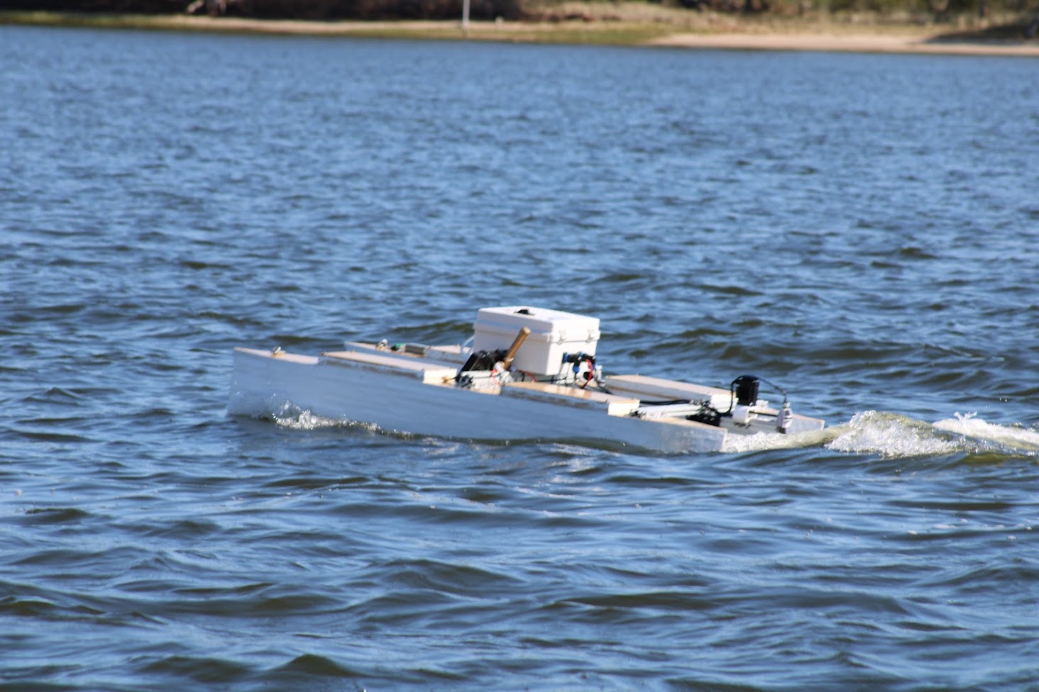
RCCF has competed in PEP since 2024. View our page on ASNE's website here for an overview of our past performance and videos from competition.
About This Documentation:
This library includes documentation for every year RCCF has competed. In each section's overview page, you can find links to our whitepaper and an overview of our performance that year. Additional pages provide meeting notes and detailed documentation. This is meant as a single repository of all the knowledge we have gained over the years of this project.
- PEP27
- PEP26
- PEP25
- Navigation
- PEP 2025 Information
- Code
- Hull Design
- Notes
- Propeller Design Research and Specifications
- Software Report
- v
- Propeller Design Research Part 2
- Rudder
- OpenProp Design Parameters
- Motor
- Motor Controllers
- Batteries
- PCB
- Notes
- Full System Layout
- PEP24
PEP27
PEP26
Online Calculators
RC Boat Calculator
https://www.radiocontrolinfo.com/information/rc-calculators/rc-boat-calculator/
B-Series Propeller Generator
https://www.wageningen-b-series-propeller.com/
Getting Started
What is this?
Hi, this is the documentation for PEP26 from technical notes to project budget. This page is to help orient new members about the basics of the competition, understand where the project is starting, and our goals for the project/competition.
Information about Promote Electric Propulsion (PEP) competition: https://www.navalengineers.org/pep26
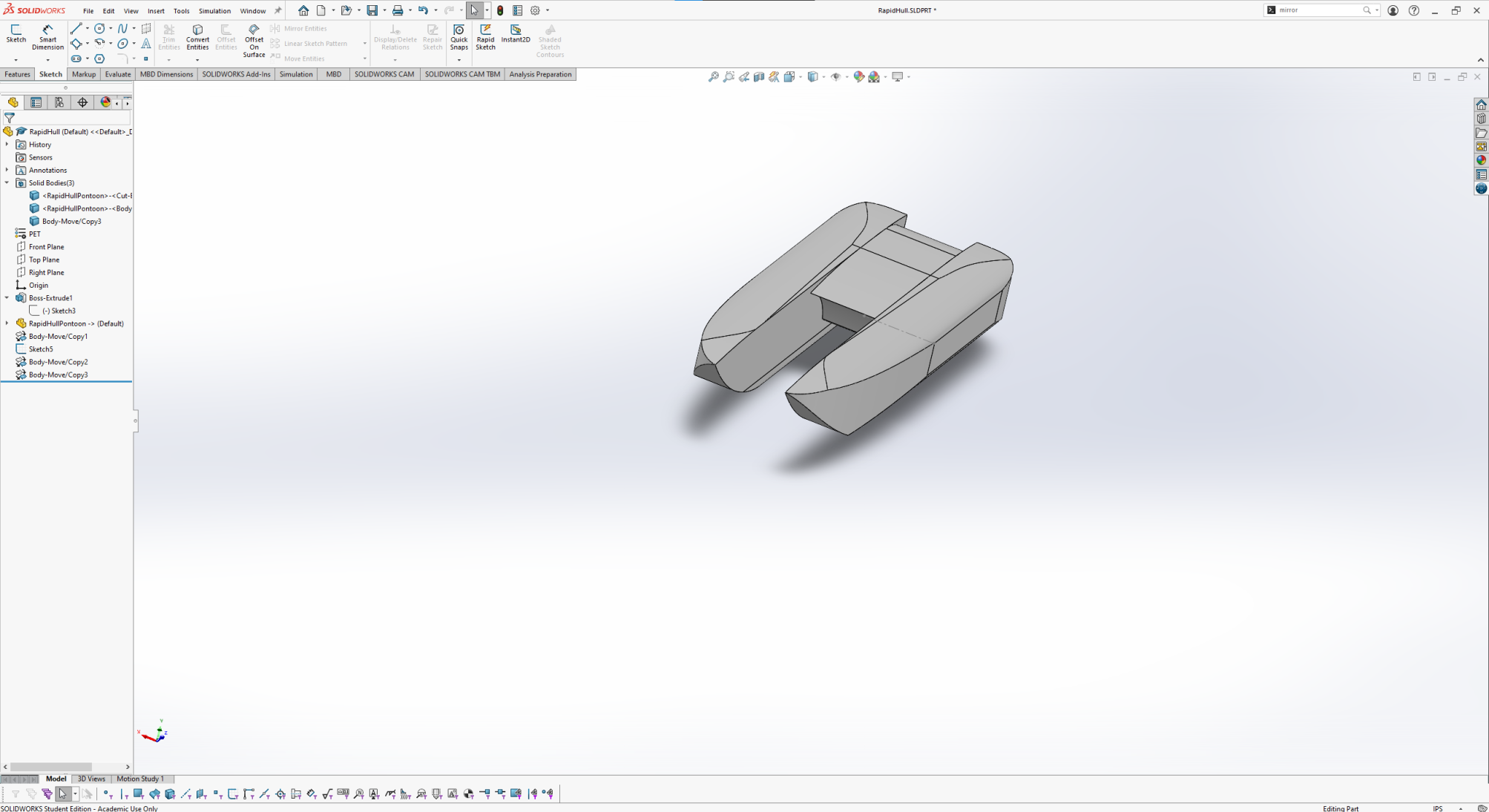
PEP26 project's main CAD tool is SolidWorks. PEP26 builds off the boat hull designed in 2025. Full SolidWorks CAD files are listed in this link: https://drive.google.com/file/d/1mpcjKZqcM0cvbklvq_0w4udm3BJp91CS/view?usp=sharing
Previous PEP teams
Team 2024 https://www.navalengineers.org/pep24
Electrical System
Parts
High Voltage System
- Contactor: AEV250-ME, rated for 500A
- 48V buck converter: converter for Stepper motor Driver
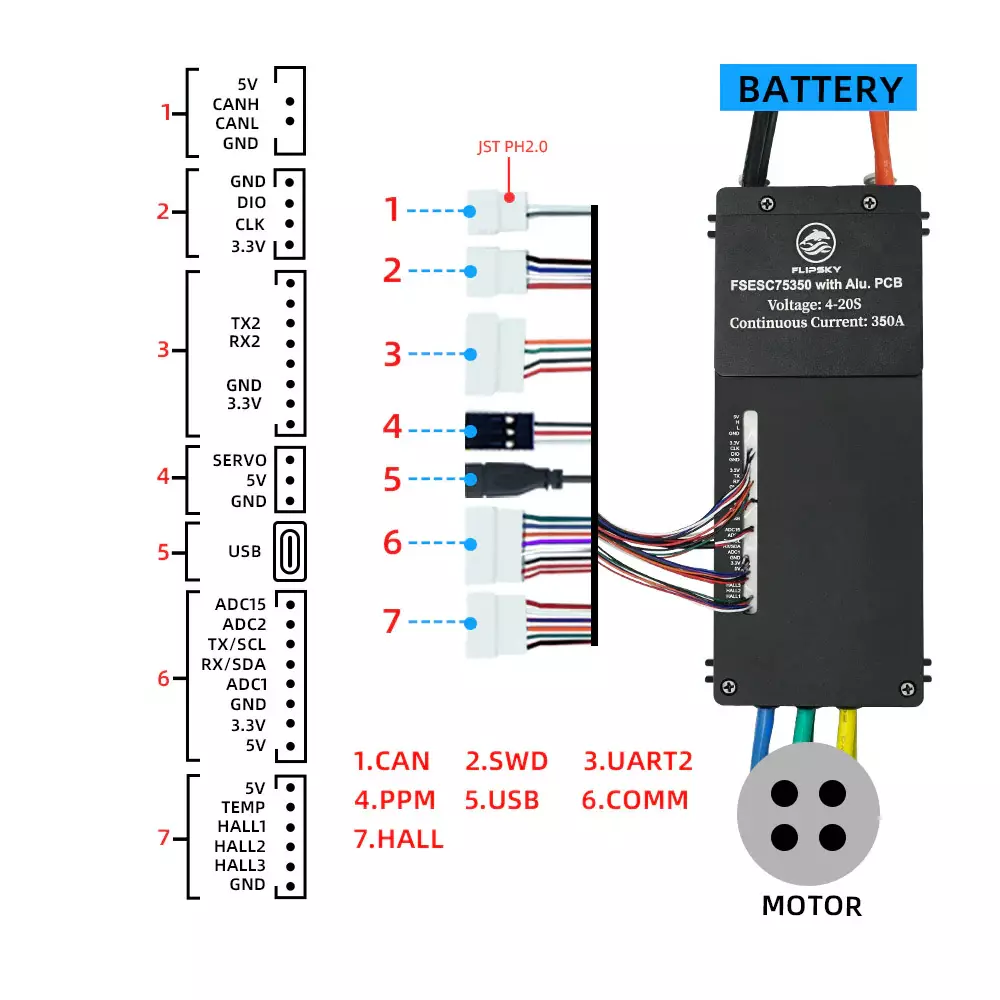
- VESC: FlipSky FSESC 7350, motor driver for Apisqueen Motor
- Main Motor: Apisqueen Motor used for forward propulsion
- Stepper motor driver: Driver for the stepper motor
- Stepper motor: used for rudder control
Antenna Enclosure
- Telemetry Radio: SiK Telemetry Radio V3
- GPS Module: HGLRC M100-5883 Compass Module
- RC Receiver
Control Box
- 14.8V LiPo
- Fuse: 40A
- Power sensing module
- 12V buck converter/regulator
- Flight Controller: CubePilot The CubeOrange+ Standard Set
- Arduino Nano/Breadboard
- Relay
- 12V to 5V converter
Others
- E-stop
- Potentiometer: measure rubber angle/movement
Wiring Diagram
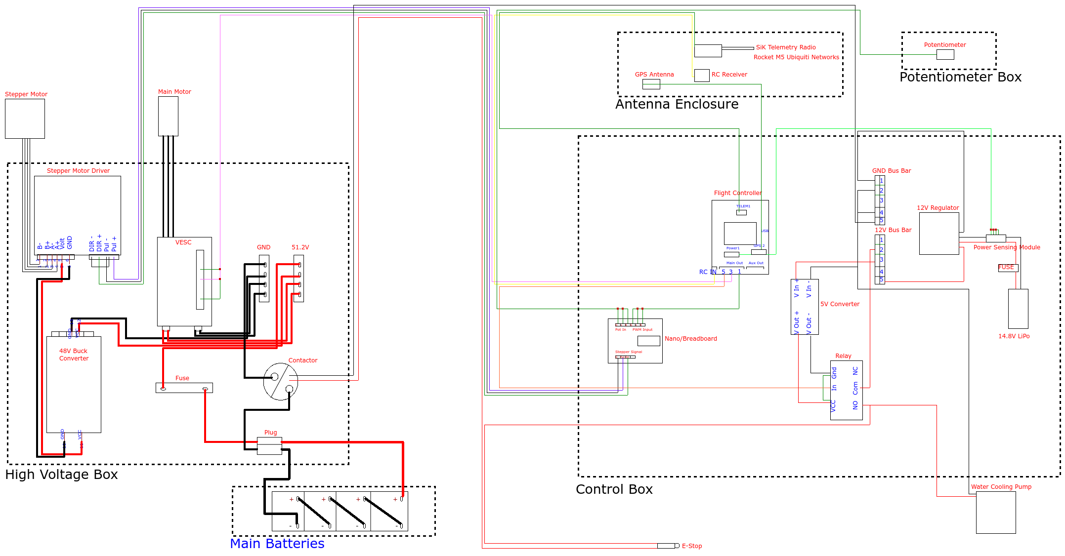
How it works
General Info
Low Voltage Initialization: The startup begins with the 4S LiPo battery, which powers the low-voltage system. The power routes through a 12V regulator and then to a 12V to 5V buck converter. This regulated 5V output powers up the Cube flight controller. The flight controller then distributes power to the RC receiver, the GPS, and the Arduino Nano used for stepper control.
High Voltage Arming: The main propulsion power relies on four 12.8 V LiFePO₄ batteries connected in series. For the high-voltage system to turn on, a sequence of safety checks must be met: the boat's safety switch must be on, the RC controller must be connected, and the arming switch on the controller must be active.
A Lua script on the ArduPilot controls sets Servo 5 output to high when the system is armed. This output is connected to a relay that completes a 12V signal circuit wired in series with the E-stop that closes a 500A rated contactor. Closing this contactor allows high voltage power to flow through a 150A fuse to the main bus bar, which then distributes power to the VESC and the 48V buck converter powering the stepper driver.
Throttle
When a throttle command is initiated by the pilot, the system relies on communication between the ArduPilot software and the VESC. The throttle input is received by the RC receiver and sent to the Cube flight controller. The flight controller outputs a PWM signal directly to the VESC. The VESC interprets this signal to dynamically control the APISQUEEN 70167 main motor, adjusting the power drawn from the 55V bus to increase or decrease thrust.
Throughout this process, the ArduPilot software streams real-time telemetry data such as battery voltage and current draw through the telemetry radio.
Steering
Steering the vessel involves translating digital control signals into precise mechanical actuation via the Arduino. A steering command from the RC controller is processed by the flight controller, which sends a PWM signal to the Arduino Nano. The Arduino Nano translates this PWM signal into the appropriate step and direction signals for the stepper driver. The stepper driver then physically rotates the 48V 5A stepper motor to move the rudder.
To maintain accurate and responsive steering, a waterproof potentiometer physically monitors the rudder's position. It feeds this positional data back into the Arduino, creating a closed control loop.
E-Stop
The emergency stop procedure is designed for physical isolation of the high-current systems while keeping the "brain" of the boat online. Pressing the E-Stop physically breaks the 12V signal loop that is wired in series with the flight controller's relay. Without the 12V signal, the 500A contactor opens. This physically severs the connection between the main LiFePO₄ batteries and the high-voltage bus bar. Power is cut to both the VESC (stopping the main motor) and the 48V regulator (stopping the rudder's stepper motor).
Because the low-voltage electronics are on a completely isolated circuit powered by the LiPo battery, the flight controller and RC receiver remain powered on. This ensures that the boat safely kills its propulsion while maintaining data logging and connection to the ground control station.
For more information, visit the GitHub.
Part Specs
Pin Out & Specs
- Voltage: 14-84V (safe for 3-20S)
-
Continuous Current: 50V/350A,75V/250A
-
Max Current: 800A
-
Supported sensors: ABI, HALL, AS5047, AS5048A
-
ERPM: 150000
-
Phase filter: Yes
-
Motor wire: 8AWG
-
Power cable: 8AWG
-
Input source: PPM, ADC, NRF, UART, PAS
-
Communication ports: USB, CAN, UART, SPI, IIC
-
CPU adaptation frequency: 168MHz (with 32F405)
-
Configurable RPM, current, voltage and power limits
-
Waterproof level (with water cooling enclosure): IP67
-
Size: 200*94.6*50mm (Including the height of water pipes and electrolytic capacitors)
-
Weight: 1.74 kg
PEP25
Navigation
Cube ArduPilot Installation Instructions
Telemetry Radio Manual
PEP 2025 Information
Major Rules
Requirements
-
Distance: 2 miles
-
Maximum Voltage: 55 V
-
Maximum Amp-Hours: 500 Ah
-
Emergency Shut Off
-
Secured Batteries
-
Maximum 5 minutes at the ramp
-
½ in. rope connection for towing
Optional
-
Carry a 30 lb OR 60 lb payload
-
Best Propeller design
-
Using OPTIMA Battery
Deadlines
|
Scores |
Completion Date |
Possible Points |
|
Bonus: Mid-Year Review |
Feb. 10, 2025 |
3 |
|
White Paper |
Mar. 25, 2025 |
20 |
|
Video Presentation |
Mar. 25, 2025 |
20 |
|
Demo Video (200m/2 min. Operation) |
Apr. 1, 2025 |
N/A |
|
Race Performance |
Apr. 15-17, 2025 |
60 |
|
Bonus (Unmanned): 60 lb payload |
Apr. 15-17, 2025 |
5 |
|
|
Total Possible Points |
108 |
Code
Temperature sensors
CAN ports : https://discuss.ardupilot.org/t/how-to-send-data-from-arduino-to-pixhawk-using-i2c/99814
Temp sensor datasheet : https://www.analog.com/en/products/ds18b20.html
Applets : https://github.com/ArduPilot/ardupilot/tree/master/libraries/AP_Scripting/applets
Ardupilot forum: https://ardupilot.org/copter/docs/common-optional-hardware.html
Temp sensor ardupilot: https://ardupilot.org/copter/docs/common-temperature-sensor.html
Pihawks with Raspberry
https://ardupilot.org/dev/docs/raspberry-pi-via-mavlink.html
Hull Design
Hull Design - General Notes
---------------------------------
Hull Composition:
The hull of our vessel has to accomplish multiple things in order to be successful.
- Don't sink
- Go fast
- Fit everything nicely
- Don't put us in debt
The first thing it has to do is not sink, as we are designing a surface vessel, not a submarine. The way a ship doesn't sink depends entirely on its hull's ability to resist taking on water during normal use. The way we have chosen to do this with our hull is by creating a composite hull, comprised of the following layers:
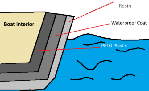
- The first (or inner) layer of PETG plastic will be 3D-printed, in panels, which provide the outer skin of the boat. PETG was chosen for its temperature resistance, general rigidity (which aids the "skeleton" in maintaining structural integrity), and water resistance after printing. It is a flexible middle-ground between PLA and TPU, having more flexibility than PLA (being less brittle) and being more rigid than TPU.
- The second (or middle) layer of the hull's skin is a roofing-grade waterproofing paste. Though plastic is not usually thought of as susceptible to water absorption, if water is absorbed into PETG plastic over time, the structural integrity of the plastic may be compromised. It may become more brittle and therefore less resistant to impacts from waves or the wakes of other boats, which is bad. So, this paste layer will prevent water from damaging the plastic underneath.
- (OPTIONAL) A second middle layer may be added if decals / art is to be added to the hull. Whatever paints / dyes are used will be sealed by the following layer, but must be placed on the outside of the opaque waterproofing layer so that it A) does not prevent the waterproofing layer from waterproofing, and B) is not obscured by the opaque paste.
- The last (outer) layer will be a translucent resin, which will act as a sealant. This final layer prevents the elements from interacting with the paints, waterproofing layer, and plastic. It will also make the boat shiny :D, and may negligibly albeit positively impact the structural integrity of the boat.
The second thing the boat hull has to do is go fast. This component is dependent on the electrical and motor teams' abilities to collaborate effectively to deliver an optimal motor for our boat. It is also, however, dependent on the hull team's ability to deliver a hydrodynamic hull.
The hull team has chosen a catamaran design for our boat. This essentially implies that the hull will have two "pontoons" which are structurally integral to the central, primary cabin (interior, below-deck room of a ship) that houses our electronics box. The basic layout for the boat is below:
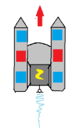
The two "pontoons" of the boat are on either side of the electrical box, annotated by the yellow lightning bolt. They are spaced as such to prevent the boat from rolling over. The pontoons will also house the 4 batteries (blue boxes) and the payloads (red boxes).
The third thing a hull has to do is fit everything nicely. Our hull will accomplish this by default; we will dimension it around the necessary components, which are listed below:
| Component | Full dimensions | Scaled dimensions | Weight |
| Battery (x4) | 12 x 9 x 7 inches | 3 x 2.25 x 1.75 in | undefined |
| Payload (x2) | undefined |
undefined |
30 lbs |
| Electrical box (x1) | 12 x 16 x 8 inches | 3 x 4 x 2 in |
undefined |
scale: 1/4
The fourth thing the hull has to do is prevent us from going into debt. The way we accomplish this is by using affordable materials, planning our production of the hull, and through testing scale models to avoid wasting excessive material. The production procedure, as it currently stands, is below:
| Step |
Procedure |
Purpose |
Status |
| 1 | decide on a hull type |
to decide on the best course of action for the mission. |
complete |
| 2 | prototype the first rudimentary iteration of the hull | to allow the team members to make decisions on the hull while they are able to comprehend it as a 3d concept | complete |
| 3 | prototype the next iterations of the hull in CAD | to allow each member to implement their own ideas on hull design; to allow each member to gain 3D CAD experience; to begin the process of figuring out the best general shape for the scale design | in progress |
| 4 | Decide on the best CAD scale prototype for testing purposes | to decide which CAD model is the most optimal; to give each member the chance to have their ideas heard and weighed | -- |
| 5 | Print the scale model / panel test | to test the effectiveness of 3D-printed hulls; to test the printers and optimize their settings for printing panels out of PETG later on; to provide data for optimizing the thickness and infill of the panels which will be printed later on | -- |
| 6 | Design the skeleton of the real boat in CAD |
the skeleton is necessary for the structural integrity of the boat, and for anchoring the panels along bulkheads. |
-- |
| 7 | Design the real hull in CAD | this step is necessary for simulations (OPTIONAL); the general shape of the hull will be required before we can break it up into individual panels. | -- |
| 8 | Break up the CAD design into panels | Each panel gets printed individually. We also need to figure out how they will be attached to the skeleton. | -- |
| 9 | Print the panels and 3D geometry | This is necessary for assembly of the final boat. | -- |
| 10 | Assembly | The final boat needs to be assembled. | -- |
| 11 | Finishing | The assembly needs to be finished (plastic welds around electrical box, apply coatings, etc...) | -- |
| 12 | Dry testing |
The Dry test is necessary for making sure the electronics won't explode. During dry testing, a single panel should be submerged in water for a few hours to determine the effectiveness of the finishing process on waterproofing the hull panels. |
-- |
| 13 | Wet testing | The Wet test is necessary for determining the performance of the boat in actual water. Leaks should be addressed in this phase, and they should be thoroughly patched. This phase is also necessary for determining if the hydrofoils are go/no-go, and if they need to be adjusted. | -- |
| 14 | Competition | :D | -- |
-------------------------------------------------
Current hull iterations:
| Author | Iteration |
Image | Description |
| Cai, Dylan, et. al | 0 |
(cardboard model) |
|
| Cai | 1 |
|
|
| Li | 1 |
|
|
| Dylan | 0 |
|
|
| Brooke | 0 |
|
|
| Anyone Else | |||
----------------------------------------------------------------------------------------------------------------------------------------------------
Materials used for final hull:
| Material |
Quantity |
Purpose |
Cost $$ |
| PETG Plastic filament | undefined | All models will be made of PETG. The final boat will use PETG panels for its skin. | undefined |
| Waterproof Material | --> Edits required | ||
| Translucent Resin (brand? type?) | undefined |
Final layer of boat will be translucent resin. It will act as a sealant. | undefined |
| Hydrofoils (type, brand, material, etc...) | --> Edits required | ||
| -- | |||
| -- |
Notes
11/08/2024
Meeting goals
Get ArduPilot up and running on Cube
Meeting Notes
What was completed?
- Installed latest ArduPilot firmware to Cube
- Issue with flashing firmware on QGC (Ubuntu), worked with APM Mission Planner (Windows)
- Once firmware updated, the FC was able to communicate with QGC
- Experimented with calibrating accelerometer and compass
- Telemetry Radio Manual
What is in progress?
- Looking in to telemetry radio - Matthew
- Goal is to have software fully integrated by the end of semester
- Working control (Thrust & Steering)
Working w/ RC Controller - Working GPS
Working Telemetry Radio
- Working control (Thrust & Steering)
What is the goal for the next meeting?
11/12/2024
Meeting goals
Meeting Notes
What was completed?
- Issue w/ QGC finding firmware seems to be fixed, able to flash autopilot firmware from QGC
- Got RC Receiver working by connecting receiber to RCIN pins on controller and forcing SBUS protocol in ArduPilot parameters
- Configured motor parameters, servo functions
- Servo 1 - Steering
- Servo 3 - Throttle
What is in progress?
What is the goal for the next meeting?
- Get PWM Control working
11/15/2024
Meeting goals
- Get PWM Control working with flight controller to control motor
Meeting Notes
What was completed?
- Researched GPS modules, trying to find one with the right connector and protocol to be recognized by AutoPilot
- Configured PWM output and got it working. Receiver is now controlling motor
What is in progress?
- Finalizing GPS modules pick
- Getting telemetry radio working
What is the goal for the next meeting?
- Get telemetry radio connection between ground station and flight controller
1/14/2025
Meeting goals
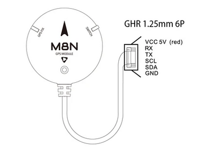
- Work on getting M8N GPS Module Connected
Meeting Notes
What was completed?
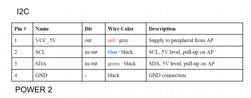
- Resoldered the wires on the GPS using these colors to connect it to I2C:
-

- Did not work
-
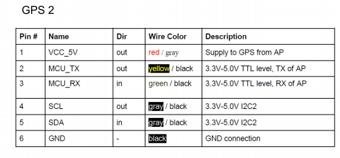
- I believe it should be this to connect it to the GPS 2 Module but unsure of how the colors line up:
-
What is in progress?
What is the goal for the next meeting?
- Resolder the 6 wires onto an 8 pin connector and test the GPS on the GPS2 Port
- If this does not work, pick out another GPS and order
Images
Propeller Design Research and Specifications
Date: 9/6/24
Meeting goals
- Research into manufacturing options
- Metal
- Resin
- ASA
- Research into propeller design
- Research into counter-rotating propellers
Meeting Notes
LINKS:
https://bblades.com/props-101/#:~:text=Rake%20is%20the%20amount%20of,outboard%20propellers%20is%2015%20degrees. -Propeller 101
https://bit.ly/4e8DVso - Tentative motor
CAESES Video Tutorials › CAESES - Design software
https://web.mit.edu/2.016/www/handouts/2005Reading10.pdf - MIT paper on propellers
Manufacturing
3D-printing for prototype and later have the propeller milled
Propeller design
We were brainstorming about the use of 2 or 3 blades due to the size of the boat. Depending on the actual power needed to lift the hydrofoil out of the water we could reduce the amount of blades used on a counter rotating prop. Since the efficiency of the counter rotating prop design is more efficient, maybe it is possible to reduce the amount of blades from 6 to 4 on the shaft.
Counter-rotating propellers
What was completed?
What is in progress?
What is the goal for the next meeting?
Images
Software Report
How, what, why?
Software Goals:
Primary
- Reliable RC Controls for long distance
- Telemetry data feed back: Primarily battery voltage, current draw
Secondary:
Control Software:
We moved away from our completely custom software setup on ESP32 last year. The ESP32 was simple and great for allowing plain RC controls, however was limited for further development. We also had no way to receive data back from the boat in real time.
- ArduPilot:
- Why: Already built library for autonomous and semi-autonomous vehicles
- Ability to tune PID controls w/ integration w/ IMU
- Ability to switch from remote to autonomous controls
- Ability to communicate with ground control station allowing for us to view position of boat, send waypoints, view real time telemetry.
- ArduPilot would also allow for control of active hydrofoils if we develop those in the future
- Why: Already built library for autonomous and semi-autonomous vehicles
Hardware Choices:
- OrangeCube Pilot: Connects directly w/ RC controller, integrated IMU,
- RPi 4: Interface with ArduPilot via WiFi for data streaming
- ESP32 controls the stepper motor by translating the PWM signal for the rudder from the Flight controller into the apropiate signals for the stepper
v
**Abstract**
Whether one is prototyping, recreating, or even creating a new unique item there is no question that 3D printing is a positively helpful tool in the process of an item going from a fantastical idea to reality. The Robotics Club of Central Florida (RCCF) has found 3D printing an essential part of bringing forth an idea to the real world; however, this process is not without its challenges. With this paper, RCCF’s Rapid 3D team presents the challenges of designing, developing, and testing a fully custom 3D printed hull designed around a central direct drive electric propulsion system. This system is based upon RCCF’s direct expertise in robotics, specifically the need to keep component interactions simple, functional, and reliable. With that in mind, the drive assembly of the boat (Rapid 3D) features an optimized propeller, selected based on diameter and pitch to maximize thrust efficiency, a submersible pod electric motor for direct drive propulsion, and a custom-geared rudder system for both enhance maneuverability and control. The power system integrates 4 LiFePO₄ and a LiPo battery, ensuring a balance of power efficiency, safety, and redundancy. \
Propeller Design Research Part 2
Date: 09/17/24
Meeting goals
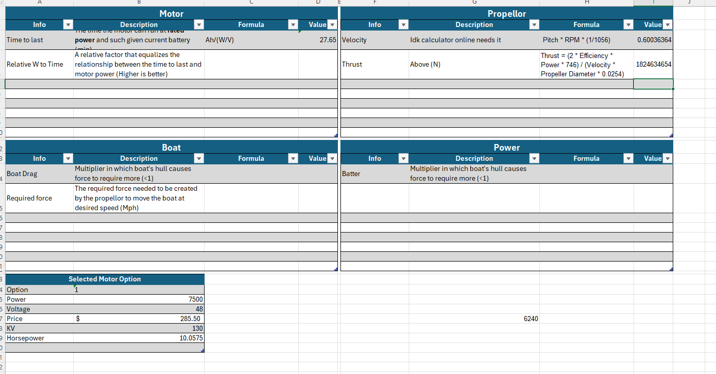
- Calculator for approximate propeller thrust given motor specifications
- Learn how to use a simulator to simulate propeller performance
- Compare calculator results to simulator results
Meeting Notes
- Propeller thrust can be calculated using:
- Thrust = (Motor power * Propeller efficiency) / Flow velocity
- Source: Propeller Performance: An introduction, by EPI Inc. (epi-eng.com)
- Flow velocity can be calculated using:
- Speed (inches/minute) = Pitch * RPM * (1 - Slip)
- Source: http://dunnritepropellers.co.nz/images/prop_tips_03.pdf
- Factors contributing to propeller slip and how to reduce propeller slip:
- Boat weight and design: The weight and design of your boat can affect how much resistance the propeller encounters in the water, which can impact prop slip.
- Engine power: If your engine is producing more power than your boat can handle, it can cause the propeller to slip in the water.
- Propeller size and design: The size and design of your boat’s propeller can impact how efficiently it moves through the water and how much resistance it encounters.
- Water conditions: Rough water or strong currents can increase the resistance your propeller encounters, which can lead to higher prop slip.
- Source: How To Reduce Prop Slip: Tips and Techniques For Better Boat Performance - Waves Weekender
- A slip of 1 or 100% means that the propeller will not advance in water.
- "Calculated propeller slip within the
- range of 5% to 25% is typical and acceptable. If slip is greater than 25%, there is likely an issue with the propeller." Prop Bite: Understanding Propeller Slip | Mercury Marine
- Propeller efficiency is related to propeller diameter. The greater the diameter, the more efficient the propeller (The propeller will be able to move more water/ produce more thrust per revolution). But the greater the propeller diameter, the more drag. So for low-speed craft, a higher diameter propeller is preferred whereas for a higher-speed propeller, a smaller diameter propeller is preferred. How Propeller Pitch and Diameter Affect Boat Performance (citimarinestore.com)
- "The main opportunities for propulsion efficiency improvements are in hull efficiency (typically 0.95–1.3), propeller open water efficiency (typically 0.55–0.70) and relative rotative efficiency (typically 0.98–1.07)" Propeller Efficiency - an overview | ScienceDirect Topics
- Selected motor: APISQUEEN 70167 7.5KW internal rotor brushless waterproof motor for hy – Underwater Thruster
What was completed?
- The calculator: https://docs.google.com/spreadsheets/d/1fZU8p28u3xLca4Ge9oelJ2ioDH1f_wty5EOEaINy_YU/edit?usp=sharing
What is in progress?
- Learn how to use a simulator to simulate propeller performance
- Compare calculator results to simulator results
What is the goal for the next meeting?
- Simulate a propeller and compare results with the calculator
Images
Rudder
9/20/2024
Balanced Barn door rudder which can either be attached from just the top or form a top and bottom, which is a rudder with a shaft through the middle which will spin the rudder.
Benefits:
- Less force needed so steer the rudder
- relatively simple to use a stepper motor with
- can be made modular
Cons:
- Fails to support big boats
- more likely to break if hits an object
- If we attach only from the top is less stable
OpenProp Design Parameters
OpenProp Design Parameters
- B-series propeller design parameters: Untitled
- B-series propeller design procedure: OptimumdesignofB-seriesmarinepropellers.pdf
1. c/D (Chord Length / Diameter Ratio)
- Description: The ratio of the chord length of the blade to the propeller diameter.
- Effects of Changing c/D:
- Higher c/D:
- Increased Lift: A larger chord length can generate more lift, which may be beneficial for high-thrust applications.
- Higher Drag: It may also increase drag, reducing overall efficiency.
- Lower c/D:
- Reduced Lift: A smaller chord length can decrease lift generation.
- Lower Drag: It typically results in less drag, improving efficiency at higher speeds but may limit thrust.
- Higher c/D:
2. Cd (Drag Coefficient)
- Description: A dimensionless number representing the drag force acting on the blades relative to the dynamic pressure and reference area.
- Effects of Changing Cd:
- Lower Cd:
- Improved Efficiency: A lower drag coefficient generally leads to better aerodynamic efficiency, allowing the propeller to produce more thrust with less energy.
- Potential for Higher Speeds: Reduced drag can enhance performance in high-speed applications.
- Higher Cd:
- Increased Resistance: A higher drag coefficient can lead to more energy loss and reduced overall performance.
- Lower Efficiency: May result in lower efficiency and increased fuel consumption or power usage.
- Lower Cd:
3. t0/D (Thickness at Hub / Diameter Ratio)
- Description: The ratio of the blade thickness at the hub to the propeller diameter.
- Effects of Changing t0/D:
- Higher t0/D:
- Increased Strength: Thicker blades can withstand greater stresses, enhancing structural integrity and cavitation resistance.
- Potential for Higher Drag: Thicker blades can increase drag, potentially reducing efficiency.
- Lower t0/D:
- Weight Savings: Thinner blades can reduce weight, which may be advantageous in lightweight applications.
- Reduced Strength: May lead to increased risk of structural failure under heavy loads or high-speed conditions.
- Higher t0/D:
4. Skew
- Description: The angle at which the blade is twisted or skewed along its length.
- Effects of Changing Skew:
- Increased Skew:
- Improved Thrust Distribution: More skew can help distribute thrust more evenly along the blade, reducing the likelihood of cavitation and improving overall performance.
- Changes in Flow Dynamics: It can alter the flow around the blade, potentially enhancing lift at specific angles of attack.
- Decreased Skew:
- More Traditional Blade Shape: Less skew may lead to a more conventional blade profile, which might not optimize performance in certain applications.
- Increased Risk of Cavitation: Less skew can concentrate forces and pressure, potentially increasing the risk of cavitation at certain operating points.
- Increased Skew:
5. Xs/D (Distance from Leading Edge to Maximum Thickness / Diameter Ratio)
- Description: The ratio of the distance from the leading edge to the point of maximum thickness to the propeller diameter.
- Effects of Changing Xs/D:
- Higher Xs/D:
- Thickness Distribution: Shifting the maximum thickness further back can alter the lift and drag characteristics, potentially improving performance at higher speeds.
- Stability: Can enhance stability and control characteristics, especially in high-performance applications.
- Lower Xs/D:
- Early Thickening: Moving the maximum thickness closer to the leading edge can increase initial lift but may lead to higher drag at certain angles of attack.
- Increased Sensitivity: Can make the blade more sensitive to changes in flow conditions, potentially affecting performance during maneuvering.
- Higher Xs/D:
Motor
9/10/2024
By looking at the possible motors that we have chosen and comparing them with power and price we have decided to go with:
Also worked on calculation in the spread sheet, Current spread sheet to calculate values(PDF):
Coming up
will need to pick out a ESC before friday.
Motor Controllers
Main motor controller (link)
We made the decision to go with the Flipsky 75350. We made this decision because of prior years experience with Flipsky controllers and they give some of the best functionality and configuration.
Pros
- High power output
- Built in water cooling
- Multiple forms of communication
- Highly configurable motor control
Cons
- Size and weight
- Overpowered for current motor selection
Specs
- Voltage: 14-84V (safe for 3-20S)
- Continuous Current : 50V/350A,75V/250A (Duration depends on external heat dissipation)
- Instantaneous Peak Current : 800A
- Supported sensors: ABI, HALL, AS5047, AS5048A
- EPRM: 150000
- Phase filter: Yes
Batteries
High Power System Batteries (link)
We will continue to use out 4 100ah Lithium Iron Phosphate (LiFe) batteries that we choose last year for our competition. These batteries were very oversized for our purposes last year but will much better suited this year with our higher power requirements. Lithium iron phosphate was chosen for it's safety to density ratio. Compared to Lithium Ion(Li-Io) or Lithium Polymer(Li-Po) LiFe is less energy dense but also comes with a more safe chemistry.
Battery Configuration
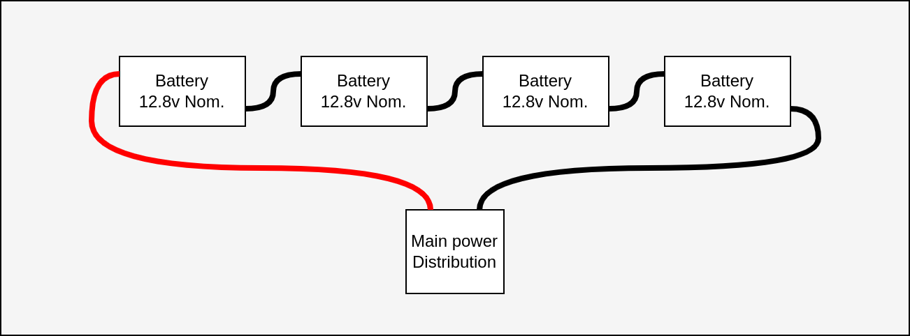
The batteries will be configured in a 4s configuration of the battery packs we use. If you consider the internal configuration of each pack we will be using a 16s battery configuration.
PCB
Old Boat PCB.zip
Notes
Notes
09/06/24
Meeting goals
Meeting Notes
List of sensors/control connections for the boat
- temp sensors
- actuator communication
- imu / GPS
- main motor
- Controller
- data collection
- e-stop control
What was completed?
What is in progress?
- motor selection
- controller selection
- PCB improvements
- battery requirements (based off motor selection)
- boat computer decision
- esp32
- rasberry pi
- flight controller
- Software
What is the goal for the next meeting?
Images
09/10/24
Meeting goals
- Basic EasyEDA design
- Example project
Meeting Notes
What was completed?
What is in progress?
What is the goal for the next meeting?
Images
Full System Layout
Full System
High Voltage System
High Voltage Supply

High Voltage Distribution

Low Voltage System
PEP24
Power and Control
Batteries
Battery 1
Capacity: 71,688mah + 17,457mah + 14,206mah = 103,351mah
Battery 2
Capacity: 90,007mah + 12,816mah = 102,823mah
Battery 3
Battery 4
PCB Iterations
V0.1 (Breadboard)
Pre-PCB design that often was multiple parts of the system that would eventually become one.
Pros
- Easy to add/change components for testing
Cons
- Unreliable connections
Components
V0.1 (Breadboard)
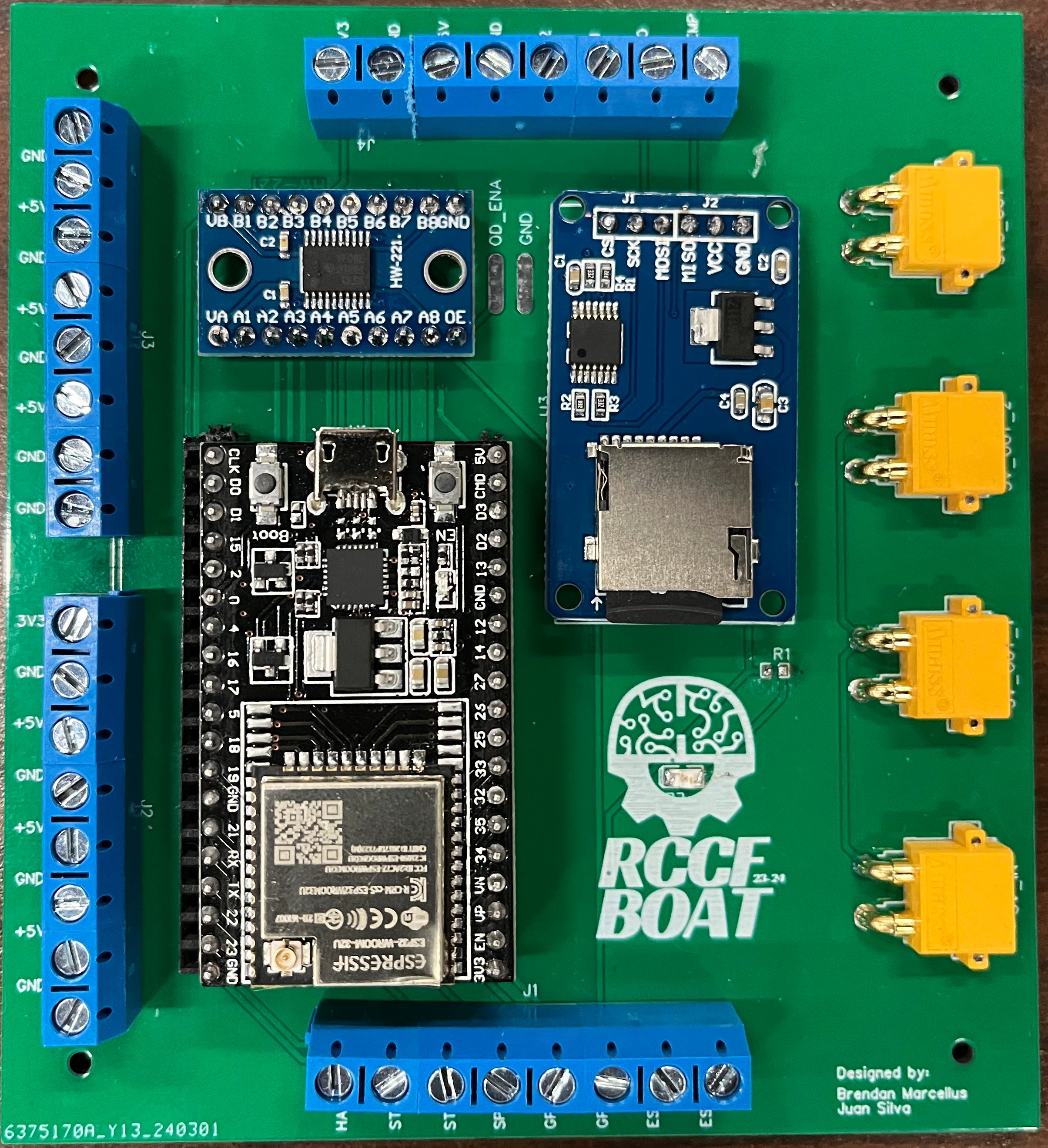
V1
Version one was created by Brandon Marcellus & Juan Silva early on in the start of the project after we had started some of the basic wiring of control and data collection.
Pros
- Organization greatly improved
- Power distribution
Cons
- Logic level shifter was not wired correctly
- Not enough IO ports were available for use
- SD Card module VCC pin was connected to 3.3V instead of 5V
V1
V 1.1 (Breadboard)
V2
PEP24 Overview
PEP24 was RCCF's first time competing.
Our boat was a catamaran constructed out of layered XPS foam wrapped in fiberglass.
This year provided a strong foundation for future years. The LIthium Iron Phosphate batteries, selected for their long life span, continued to power the team through the next two years.
2024 Whitepaper:
2024 Google Photos
No Comments