
Electrical System
Parts
High Voltage System
- Contactor: AEV250-ME, rated for 500A
48v48V buck converter: converter for Stepper motor DriverVESC:VESC: FlipSky FSESC73507350, motor driver for Apisqueen Motor- Main Motor: Apisqueen Motor used for forward propulsion
- Stepper motor
driver:driver: Driver for the stepper motor - Stepper motor: used for rudder
control.control
Antenna Enclosure
- Telemetry Radio
- GPS Module
- RC Receiver
Control Box
- 14.8V LiPo
- Fuse: 40A
- Power sensing module
- 12V buck converter/regulator
- Flight Controller
- Arduino Nano/Breadboard
- Relay
- 12V to 5V converter
Others
- E-stop
- Potentiometer: measure rubber angle/movement
Wiring Diagram
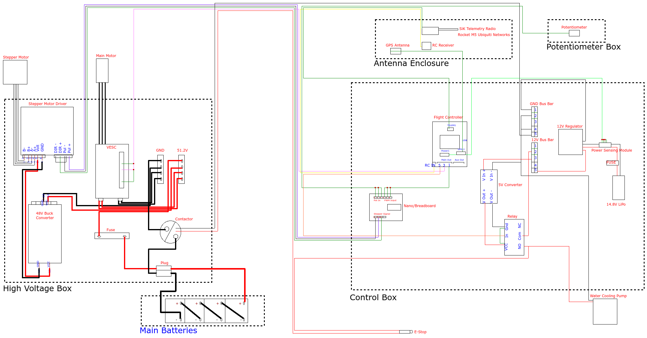
How it works
General Info
Low Voltage Initialization: The startup begins with the 4S LiPo battery, which powers the low-voltage system. The power routes through a 12V to 5V buck converter. This regulated 5V output powers up the Cube flight controller. The flight controller then distributes power to the RC receiver, the GPS, and the Arduino Nano used for stepper control.
High Voltage Arming: The main propulsion power relies on four 12.8 V LiFePO₄ batteries connected in series. For the high-voltage system to turn on, a sequence of safety checks must be met: the boat's safety switch must be on, the RC controller must be connected, and the arming switch on the controller must be active.
Contactor Engagement: Once armed, the flight controller activates a relay. This relay completes a 12V signal circuit wired in series with the E-stop—that closes a 500A rated contactor. Closing this contactor allows high voltage power to flow through a 150A fuse to the main bus bar, which then distributes power to the VESC and the 48V buck converter powering the stepper driver.
Throttle
When a throttle command is initiated by the pilot, the system relies on rapid communication between the ArduPilot software and the VESC. The throttle input is received by the RC receiver and sent to the Cube flight controller. The flight controller outputs a PWM signal directly to the VESC. The VESC interprets this signal to dynamically control the APISQUEEN 70167 main motor, adjusting the power drawn from the 55V bus to increase or decrease thrust.
Throughout this process, the ArduPilot software streams real-time telemetry data such as battery voltage and current draw over WiFi to the Raspberry Pi for monitoring.
Steering
Steering the vessel involves translating digital control signals into precise mechanical actuation via the Arduino. A steering command from the RC controller is processed by the flight controller, which sends a PWM signal to the Arduino Nano. The Arduino Nano translates this PWM signal into the appropriate step and direction signals for the stepper driver. The stepper driver then physically rotates the 48V 5A stepper motor to move the rudder.
To maintain accurate and responsive steering, a waterproof potentiometer physically monitors the rudder's position. It feeds this positional data back into the Arduino, creating a closed control loop.
E-Stop
The emergency stop procedure is designed for immediate physical isolation of the high-current systems while keeping the "brain" of the boat online. Pressing the E-Stop physically breaks the 12V signal loop that is wired in series with the flight controller's relay. Without the 12V signal, the 500A contactor instantly opens. This physically severs the connection between the main LiFePO₄ batteries and the high-voltage bus bar. Power is immediately cut to both the VESC (stopping the main motor) and the 48V regulator (stopping the rudder's stepper motor).
Because the low-voltage electronics are on a completely isolated circuit powered by the LiPo battery, the flight controller and RC receiver remain powered on. This ensures that the boat safely kills its propulsion while maintaining data logging and connection to the ground control station.